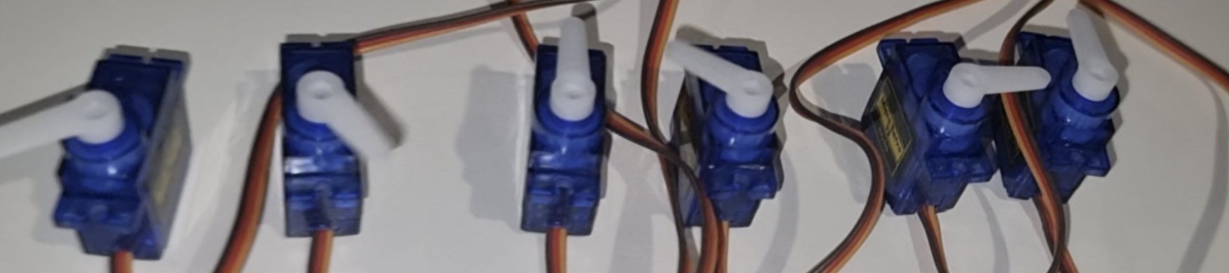
Before touching any real hardware, I did initial research to settle on a motor and a microcontroller board. Landed on continuous rotation servos, expecting that they accepted specific angle-position and rotation-direction commands having used regular 180° servos in previous works. This would let each dial's rotation angle be matched to a display symbol via a lookup table. Stepper motors and other motor types were avoided early on, mainly due to the added complication of needing a dedicated motor encoder per motor.
For the microcontroller, an Arduino Mega was the initial choice, picked for its surplus of pins for connecting the various peripherals the project would eventually need.
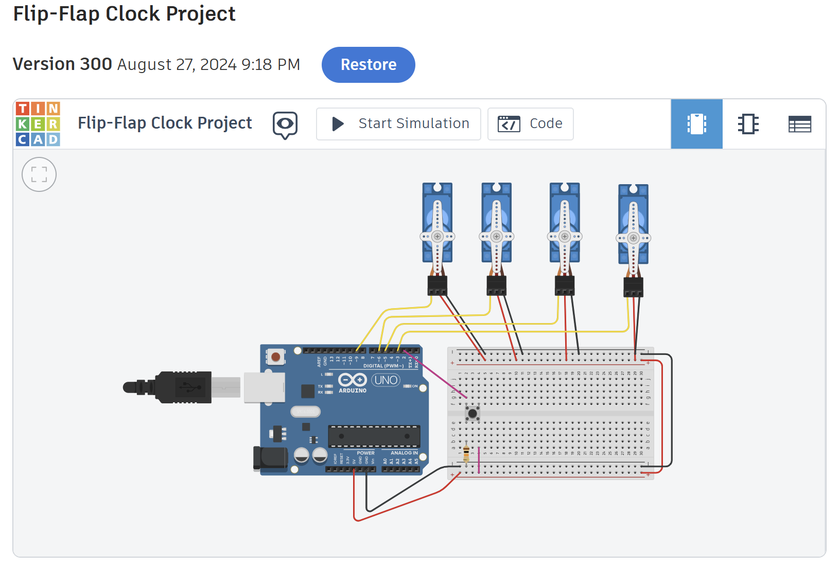
Put both together into a rudimentary proof-of-concept circuit in Tinkercad, including a button to trigger a full riffle refresh of the display. Built late in the night on the 27th.
Current Aim:
A desk clock that keeps time using a split-flap display and is powered by being connected to a computer.
Notes:
Through building this in Tinkercad and testing, I realised that Tinkercad was not only limited in the parts available but also in simulation efficiency. I had to use regular 180° servos to emulate continuous servos and an Arduino Uno in place of the planned Mega. When the simulation would run, it would progress in microseconds, which is clearly far too slow to test any function to completion.
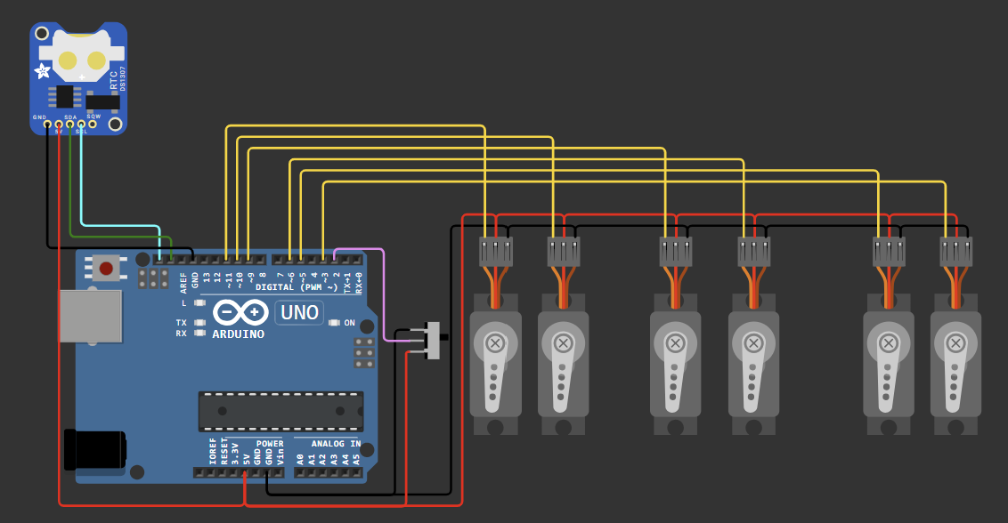
After my frustrations with Tinkercad, I moved circuit simulation over to Wokwi.com. It's a much needed step up from Tinkercad, having a near-realtime speed and a larger library of circuit components, letting me simulate the project far more accurately.
Alongside the changeover, I added a real-time clock module to the circuit to begin integrating proper timekeeping into the design and switched the button for a servo enable switch.
I also purchased my initial electronics so I could start prototyping the design at my desk. An Arduino Mega, a DS3231 RTC, SG90 continuous servos, and some general electronic kit parts marked the start of the prototyping front.
Current Aim:
A desk clock that can retain accurate timekeeping if power is unplugged, but still needs USB power to the Arduino to function.
Notes:
I still had to use 180° servos and an Arduino Uno in Wokwi, Wokwi does however offer the ability to code your own custom device but for simplicity I didn't take that route. Looking back, I should have coded my own continuous servo model, as it would have surfaced my fatal flaw before I'd already ordered the parts.
My first parts order came in today with everything needed for a first prototype, plus a few spares just in case. The test code was simple, autonomously step each of the six spools through angles every couple of seconds while the RTC reports the current time to the Arduino IDE console.
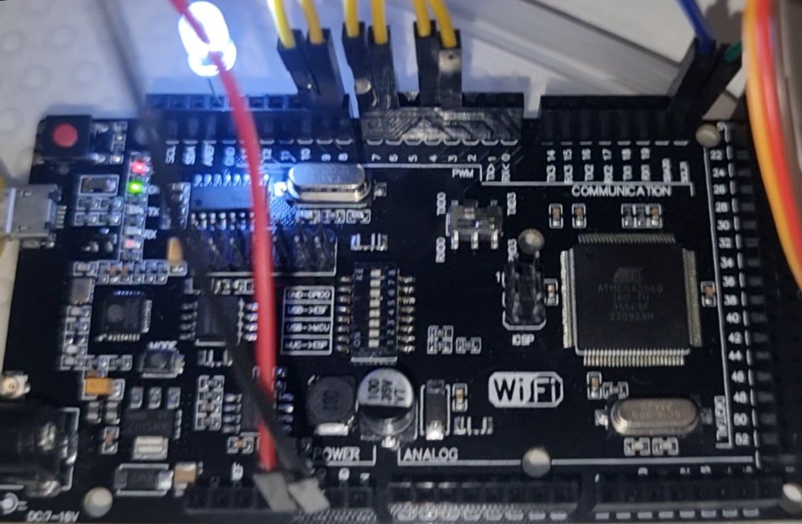
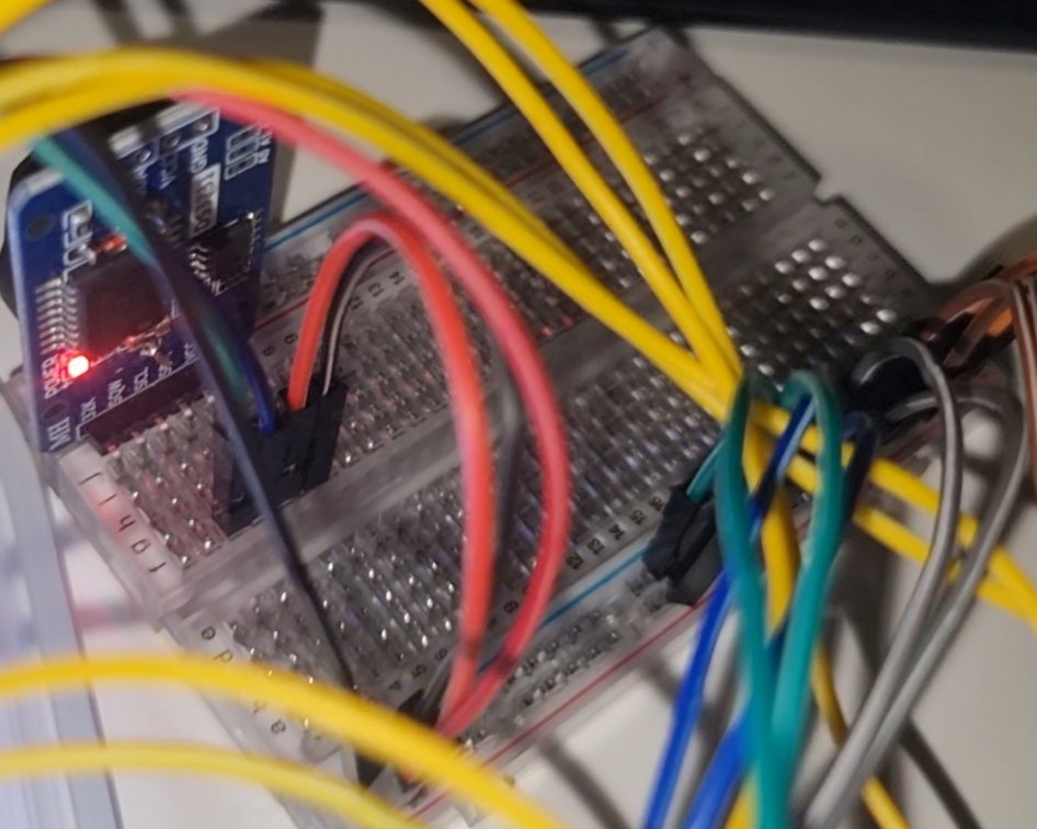
Plugged everything in, using a breadboard as an intermediary, and uploaded the code to the Arduino. I had some initial trouble getting my computer to recognise the Mega as the board I'd bought came with a non-standard "CH340C" USB-to-serial chip. After tracking down and installing the CH340C driver, I was able to upload code.
During testing, the RTC returned the correct time to the console without issue. The servos were a different story however... Instead of ticking clockwise in neat increments, some weren't spinning at all, others were spinning continuously, and a few were even spinning counter-clockwise. Prompted to do a quick google search, I discovered that continuous rotation servos are really just glorified DC motors with a built-in encoder. A continuous servo takes a value between 0-180°, where, 0-89° means "rotate clockwise", 90° means "stop", and 91-180° means "rotate counter-clockwise". To my surprise, there was no way to request an exact angle. My original assumption, that I could rotate to exact defined angles in one direction, was wrong. This sent me on a hunt to find new actuators for the split-flap spools.
Current Aim:
For all six servos to advance in increments only in one direction on Arduino boot and for the RTC to return correct time data.
Notes:
A good lesson in doing robust research and planning before dropping the hammer on a large order of parts. As a uni student, my budget was tight for this project, but I still wanted to design something cool for my desk. This put into perspective the importance of planning and simulation software. After all, on much larger projects in industry, planning and simulation saves a company the cost of physical materials and the lead times on delivery per would-be prototype. Clearly I need to go back to the drawing board.
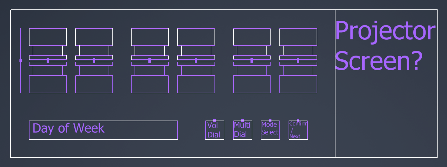
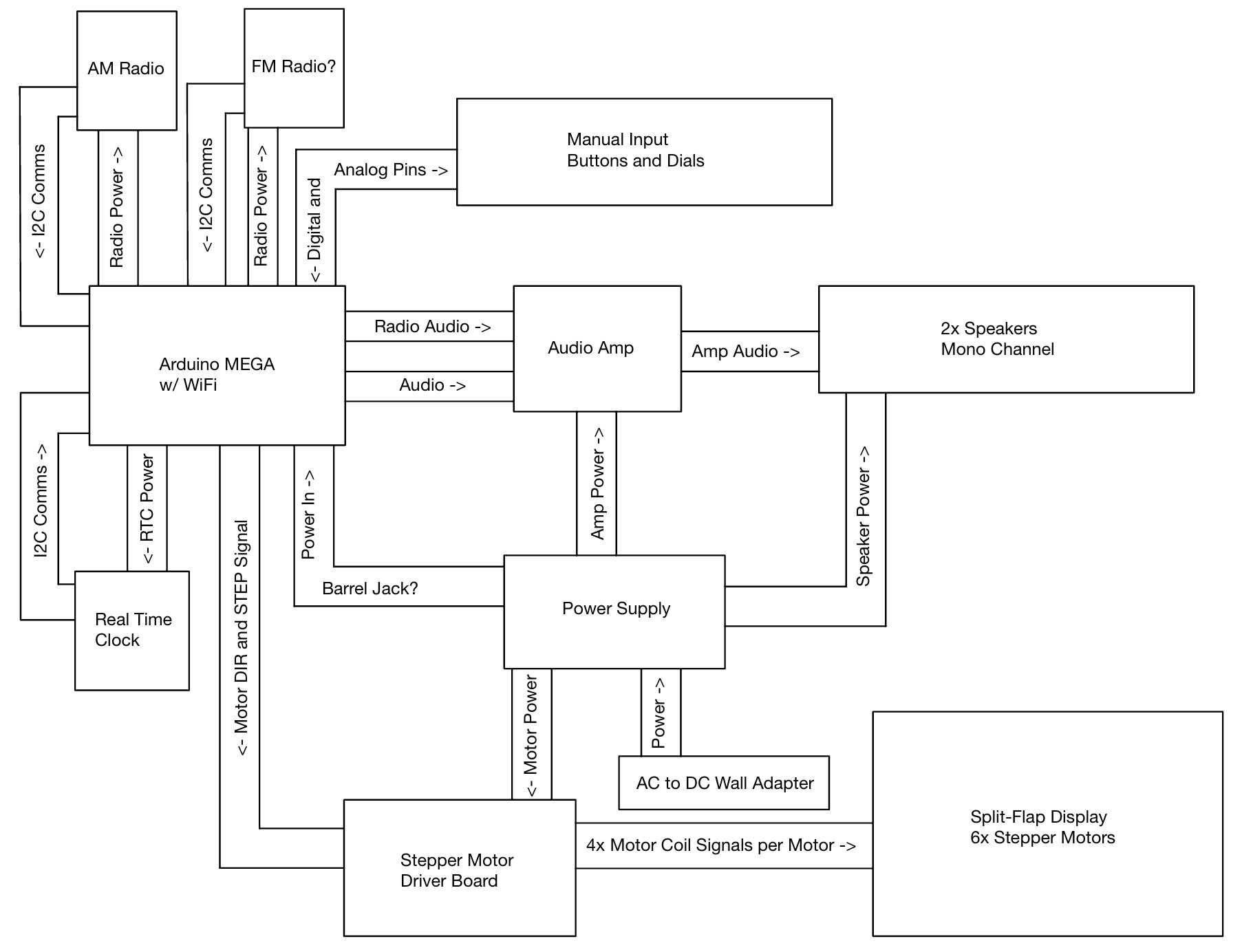
Locked in the final dial arrangement and overall footprint (300 x 150 x 80mm). Each dial will use its own stepper rather than a shared cam-driven mechanism, trading some mechanical simplicity for independent control and easier debugging later on.